Creating a tilted fluid level surface
You can use a polyline set, point set or tri-mesh surface to create a 3D grid surface that can be assigned as a tilted fluid level surface. Use The Create Surface workflow (PREPARE > Surfaces > Create Surface) to create a surface based on input data and without input data.
The tilted fluid contact surfaces are sampled once per grid cell at the cell center location.
- On the Data tab, select source type and additional marker set from the drop-down list. Select the surface type as Other Surfaces and all events in the selected source, and their underlying data representations, are shown in the table. You can change the Output description and representation for the surface.
- On the Output Geometry tab, specify the origin and dimensions of the surface . Use the 'Autofill from Input' button to use the geometry settings from the selected event in the input data.
- On the Method tab, select the method to interpolate the surface.
- Select 'Without Input' option at the top of the form.
- On the Output Geometry tab, specify the origin and dimensions of the surface. Use the 'Autofill' button to open the 'Autofill Output Geometry' dialog. Select a domain object to derive the lateral extent and resolution of your output surface.
- On the Method tab, select Create flat surface or Sequential Gaussian Simulation (SGS) in the drop-down list. Select Fluid contact in Type and specify the depth in TVDSS along with Dip and Dip azimuth in subsequent underlying entries. For SGS distribution, specify the geostatistical parameters such as variogram type, range, standard deviation and seed number.
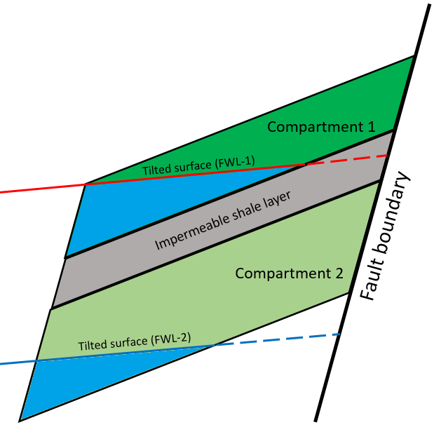
Illustration showing tilted fluid surfaces extending up to compartment boundaries. click to enlarge
Important
The tilted fluid level assigned to one or more compartments must extend up to the compartment boundaries. An error message is displayed if the surface penetrates the compartment partially.